Sharp R-305MR Especificaciones
Busca en linea o descarga Especificaciones para Chimeneas Sharp R-305MR. Sharp R-305MR Specifications Manual de usuario
- Pagina / 47
- Tabla de contenidos
- MARCADORES

- Important 2
- Safety Considerations 3
- Introduction 4
- Codes and Standards 4
- Electrostatic Discharge (ESD) 5
- Precautions Procedure 5
- Location 7
- Location Relative to Cooling 9
- Equipment 9
- Air for Combustion and 9
- CONDENSATE TRAP 10
- Figure 7 11
- Condensate Trap-Horizontal 12
- Orientation 12
- Horizontal Drain Trap Grommet 13
- (MODULATING UNITS) 14
- Condensate Drain Connection 15
- _'-=TEE 16
- RIGHT SIDE DRAIN ELBOW 16
- INSTALLATION 17
- Return Air Connections 18
- DOWN FLOW INSTALLATION 18
- Supply Air Connections 18
- JFloorandPlenumOpening 19
- Figure20 Dimensions 19
- HORIZONTAL INSTALLATION 20
- Suspended Furnace Support 21
- Roll-Out Protection 22
- Bottom Return Air Inlet 22
- Side Return Air Inlet 22
- Filter Arrangement 23
- Air Ducts 25
- GAS PIPING 25
- Gas Pipe Grommet 26
- ELECTRICAL CONNECTIONS 27
- BOX L ............ ' I 28
- 24-V Wiring 29
- Alternate Power Supplies 30
- /4,ojr T \ 31
- Materials 32
- Venting Systems 32
- MATERIAL PIPE FITTINGS 33
- SOLVENT CEMENT AND 33
- DESCRIPTION 33
- Figure41 l UpflowRightVent 34
- Figure 43 _Downflow Left Vent 35
- Figure 44 35
- Downflow Right Vent 35
- Locating the Vent Termination 37
- For single pipe vent 38
- Guidelines 39
- Configure the Furnace 40
- Combustion Air Pipe Adapter 41
- Sidewall Terminations 42
- Inducer Outlet Restrictor 43
- Altitude 46
- Table 15 47
Indice de contenidos
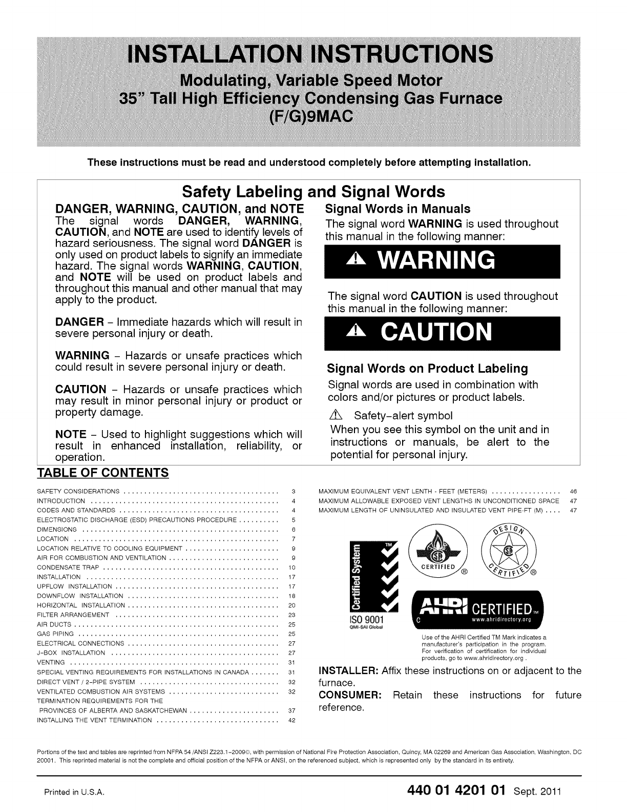
These instructions must be read and understood completely before attempting installation.Safety Labeling and Signal WordsDANGER, WARNING, CAUTION, and
d. TWO OPENINGS OR VERTICAL DUCTS require 1square inch (25.4 square mm)of free area per 4,000Btuh (550 mm2/kW) for combined input of all gasappliances
ii:ii! ii i iit ¸Figure 7Upflow Trap ConfigurationCondensateTrapRelief PortVent Pipe ClampVent Elbow ClampPlugsElbowCollector BoxPlugpRelief PortPres
Figure 8 I Unconverted Factory Configuration as viewed in the Downflow orientationA_ emove pressure switch tube fromfront of pressure switch.Remove re
Figure 9 1Drain Trap GrommettrapHorizontal Drain Trap GrommetAl1348NOTE: The condensate trap extends below the side of thecasing in the horizontal pos
Figure 10 1Unconverted Factory Configuration as viewed in the Horizontal Left orientationRemove trap fromcollector box.If alternate vent positionis re
iiiii! ii i iit ¸Figure 11 _Unconverted Factory Configuration as viewed in the Horizontal Right orientation(_) emove plug fromcollector box.DO NOT DI
Figure 12Example of Field Drain AttachmentOPEN STANDPIPE FORA/C ORHUMIDIFIERDRAINU_'-=TEETO OPENDRAINFor Right Side Condensate Drain:1.Al1276Remo
12. If the "Z" pipe does not extend through the casing, slide apiece of field supplied CPVC through the grommet in thecasing, otherwise, go
openings using light assistance or a probe can be inserted forsampling the air stream. The cover attachment shall preventleaks.Connect supply-air duct
JFloorandPlenumOpeningFigure20 DimensionsA96283NOTE: It is recommended that the perforated supply-air ductflanges be completely removed from furnace w
Required Notice for Massachusetts Installations(a)ImportantThe Commonwealth of Massachusetts requires compliance with regulation 248 CMR as follows:5.
Table 5FURNACECASI NG WIDTHIN, (mm)Opening Dimensions - in. (mm)PLENUM OPENING FLOOR OPENINGAPPLICATIONA B C DUpflow Applications on Combustible or No
FIRE, EXPLOSION, AND CARBON MONOXIDEPOISONING HAZARDFailure to follow this warning could result in personalinjury, death, or property damage.Do not in
Figure 25 I Working Platform for Attic InstallationCOMBUSTION - AIR PIPE __ VENT(SEE VENTING SECTION)(305 mm) MIN HORIZONTAL PIPESECTION IS RECOMMENDE
Filter ArrangementFIRE, CARBON MONOXIDE AND POISONINGHAZARDFailure to follow this warning could result in personalinjury, or death.Never operate a fur
External Filter Cabinet ConfigurationsFigure 29 1Accessory Side Filter RackL10F02717._,1_,,i_ 3/8,, 1/2"-1_,_--1 1/4 '' /I TABS"--
Air DuctsGeneral RequirementsThe duct system should be designed and sized according toaccepted national standards such as those published by: AirCondi
Table 8NOMINALIRONPIPESIZEIN.(aM)1/2(13)3/4 (19)1 (25)1-1/4(32)1-1/2(39)Maximum Capacity of PipeLENGTH OF PIPE - FT (M)INTERNALDIA, 10 20 30 40 50IN.(
Figure 33 _Gas EntryLeft SideGas Entry.Gas PipeGrommet Required ForDirect Gas Pipe GrommetRequirecVent Applications. ForDirectVent ApplicationsELECTRI
The J-Box cover, mounting bracket and screws are shipped inthe loose parts bag included with the furnace. The J-Box canFigure 34 ITypical 2-Stage Fiel
8.9.Figure 37Attach furnace J-Box cover to mounting bracket withscrews supplied in loose parts bag. Do not pinch wiresbetween cover and bracket.Comple
Safety ConsiderationsFIRE, EXPLOSION, ELECTRICAL SHOCK, ANDCARBON MONOXIDE POISONING HAZARDFailure to follow this warning could result in dangerousope
Refer to the instructions supplied with thecommunicating wall control for complete details.Alternate Power SuppliesThis furnace is designed to operate
ii,lii! ii i iit ¸Figure 39 (CONT.) [Variable Speed Furnace Control for ECM Blower Motor (Modulating)COMMUNICATIONCONNECTORMODEL PLUGSWITCHES ANDBLOW
Bien suivre les indications du manufacturier Iors de I'utilisationde I'appr_t et du ciment et ne pas utitiser ceux-ci si la dated'expir
crawl space) and the space is well isolated from the livingspace or garage. Combustion air requirements for this optionare the same as the requirement
Figure41 l UpflowRightVentAny other unusedknockout may be usedfor combustion airconnection.Figure 42 l Upflow Left VentRotate vent elbow torequired po
ii,lii! ii i iit ¸Figure 43 _Downflow Left VentRotate vent elbow torequired position.®DOWNFLOW LEFT CONFIGURATION©(_) Attach vent pipe adapter with g
Figure 45 1Downflow Vertical Vent Figure 47 _Vent Pipe Flush with AdaptorVENT PIPE ADAPTER WITH GASKETINSTALLED ON FURNACE VENTPIPE IS CUT FLUSH WITH
Locating the Vent TerminationGeneralNOTE: Termination Requirements for the Provinces ofAlberta and Saskatchewan are located at the end of thissection.
Figure 51IVent TerminationsOVERHANG OR ROOF /MAINTAIN 12 IN.(ELBOW PARALLELTO WALL)CLEARANCEABOVE HIGHESTANTICIPATED SNOWLEVEL OR GRADE,WHICHEVER ISGR
ii,lii! ii i iit ¸Figure 53 _Vent Pipe Termination for Non-Direct Vent and Ventilated Combustion Air SystemRoof Terminatbn (Preferred)(305mm)minimum
12.Maintain a 1-in. (25 mm) clearance from combustiblematerials to supply air ductwork for a distance of 36-in.(914 mm) horizontally from the furnace.
Configure the FurnaceCARBON MONOXIDE POISONING HAZARDFailure to follow this warning could result in personal injury ordeath.To route the vent pipe and
Figure56 _Horizontal Right Vent Configuration_==_ ALTERNATECOMBUSTIONCONNECTmONSHORIZONTAL RIGHT, VERTICAL VENTRepresentative drawing Ol]ly, some mode
13. While cement is still wet, twist pipe into socket with1/4-in. turn. Be sure pipe is fully inserted into fittingsocket.14. Wipe excess cement from
NOTE: For applications using vent pipe option indicated bydashed lines in Figure 52 and Figure 53, rotate vent elbow 90°from position.3. Disassemble l
Figure 59 1Direct Vent Termination Clearance[] VEHTTERMINAL \\\\\ _ AIR SUPPLY INLETAREAWHERE TERMINAL IS NOT PERMITEDItemABCDEFGHClearanceDescription
iiiii! ii i iit ¸Figure 60 _Other than Direct Vent Clearance - Ventilated Combustion Air OptionI,iH-fltXi AIR SUPPLY INLETD VENT TERMINAL \ Y_":
Table 12 MAXIMUM EQUIVALENT VENT LENTH - Feet (Meters)Note: Maximum Equivalent Vent Length (MEVL) does NOT include elbows or terminationsUse Table 14
Table 14 DEDUCTIONS FROM MAXIMUM EQUIVALENT VENT LENGTH - Feet (Meters)Pipe Diameter (in): 1-1/2 2 2-1/2 3* 4*Mitered 90 ° Elbow 8 (2.4) 8 (2.4) 8 (2.
Duct Systems• US and CANADA: Air Conditioning ContractorsAssociation (ACCA) Manual D, Sheet Metal and AirConditioning Contractors National Association
Figure 2Dimensions615/14[17&1] 23_10[170.1]• 2611/16_[678.11_s3t8lsTo.ol251/8_lea&7]7/8 _ _ AIR INTAKECsCONDENSATE DRAIN TRAP _ 176.L_LOCATION
LocationPERSONAL INJURY AND/OR PROPERTY DAMAGEHAZARDImproper use or installation of this furnace may result in3remature furnace component failure. Thi
Figure3 1MultipoiseOrientationsAIRFLOWTHE BLOWER iS LOCATEDTOTHE RIGHT OFTHEBURNER SECTION, ANDAIR CONDiTiONED AiR iSDISCHARGED TO THE LEFT.THE BLOWER
Location Relative to CoolingEquipmentThe cooling coil must be installed parallel with, or on thedownstream side of the unit to avoid condensation in t
Relacionado con productos y manuales para Chimeneas Sharp R-305MR
 (41 paginas)
(86 paginas)
(91 paginas)
(56 paginas)
(41 paginas)
(86 paginas)
(91 paginas)
(56 paginas)
© 2020, manymanuals.es. Todos los derechos reservados | 0.021 s |
 Manymanuals.com
 Manymanuals.de
 Manymanuals.fr
 Manymanuals.it
 Manymanuals.pl
 Manymanuals.cz
 Manymanuals.es
 Manymanuals-pt.com
Comentarios a estos manuales