Sharp R-332 Manual de usuario
Busca en linea o descarga Manual de usuario para Microondas Sharp R-332. GP1F31T/R, GP1F32T/R, GP1F33TT/RR/RT, GP1C331/331A/332 Manual de usuario
- Pagina / 9
- Tabla de contenidos
- MARCADORES
Indice de contenidos
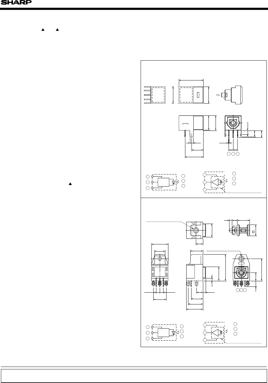
GP1F31T/R, GP1F32T/R,GP1F33TT/RR/RT,GP1C331/331A/332/333/334/335GP1F31T/R, GP1F32T/R, GP1F33TT/RR/RT, GP1C331/331A/332/333/334/335 Outline Dimensions
GP1F31T/R, GP1F32T/R, GP1F33TT/RR/RT, GP1C331/331A/332/333/334/335 Absolute Maximum RatingsParameter Symbol Rating UnitSupply voltageInput voltagePow
GP1F31T/R, GP1F32T/R, GP1F33TT/RR/RT, GP1C331/331A/332/333/334/335 Electro-optical Characteristics(1) TransmitterGP1F31T/GP1F32T/GP1F33TT/Transmittin
GP1F31T/R, GP1F32T/R, GP1F33TT/RR/RT, GP1C331/331A/332/333/334/335 Mechanical CharacteristicsFig.1 Measuring Method of Optical Output Coupling With F
GP1F31T/R, GP1F32T/R, GP1F33TT/RR/RT, GP1C331/331A/332/333/334/335Fig.4 Measuring Method of JitterGP1F31T/GP1F32T/GP1F33TT/GP1F33RTUnit to be measured
GP1F31T/R, GP1F32T/R, GP1F33TT/RR/RT, GP1C331/331A/332/333/334/335Fig.5 Muximum Input Optical Power Level/Minimum Input Optical Power Level Measuring
GP1F31T/R, GP1F32T/R, GP1F33TT/RR/RT, GP1C331/331A/332/333/334/335Fig.8 Measuring Method of JitterOscilloscopeTrigger : CH1Storage modeSweep : AUTO/NO
GP1F31T/R, GP1F32T/R, GP1F33TT/RR/RT, GP1C331/331A/332/333/334/335Fig.10 System Configuration ExampleCD/DAT/BS TunerPCMsignalModulation IC(LZ92F39)Dri
115Application CircuitsNOTICE●The circuit application examples in this publication are provided to explain representative applications ofSHARP devices
Mas documentos para Microondas Sharp R-332

Relacionado con productos y manuales para Microondas Sharp R-332
 (40 paginas)
(98 paginas)
(12 paginas)
(59 paginas)
(32 paginas)
(40 paginas)
(107 paginas)
(24 paginas)
(12 paginas)
(12 paginas)
(44 paginas)
(24 paginas)
(16 paginas)
(16 paginas)
(24 paginas)
(36 paginas)
(27 paginas)
(36 paginas)
(12 paginas)
(40 paginas)
(98 paginas)
(12 paginas)
(59 paginas)
(32 paginas)
(40 paginas)
(107 paginas)
(24 paginas)
(12 paginas)
(12 paginas)
(44 paginas)
(24 paginas)
(16 paginas)
(16 paginas)
(24 paginas)
(36 paginas)
(27 paginas)
(36 paginas)
(12 paginas)
 (54 paginas)
© 2020, manymanuals.es. Todos los derechos reservados | 0.034 s |
 Manymanuals.com
 Manymanuals.de
 Manymanuals.fr
 Manymanuals.it
 Manymanuals.pl
 Manymanuals.cz
 Manymanuals.es
 Manymanuals-pt.com
Comentarios a estos manuales